VgaSwitch
VGA Switch

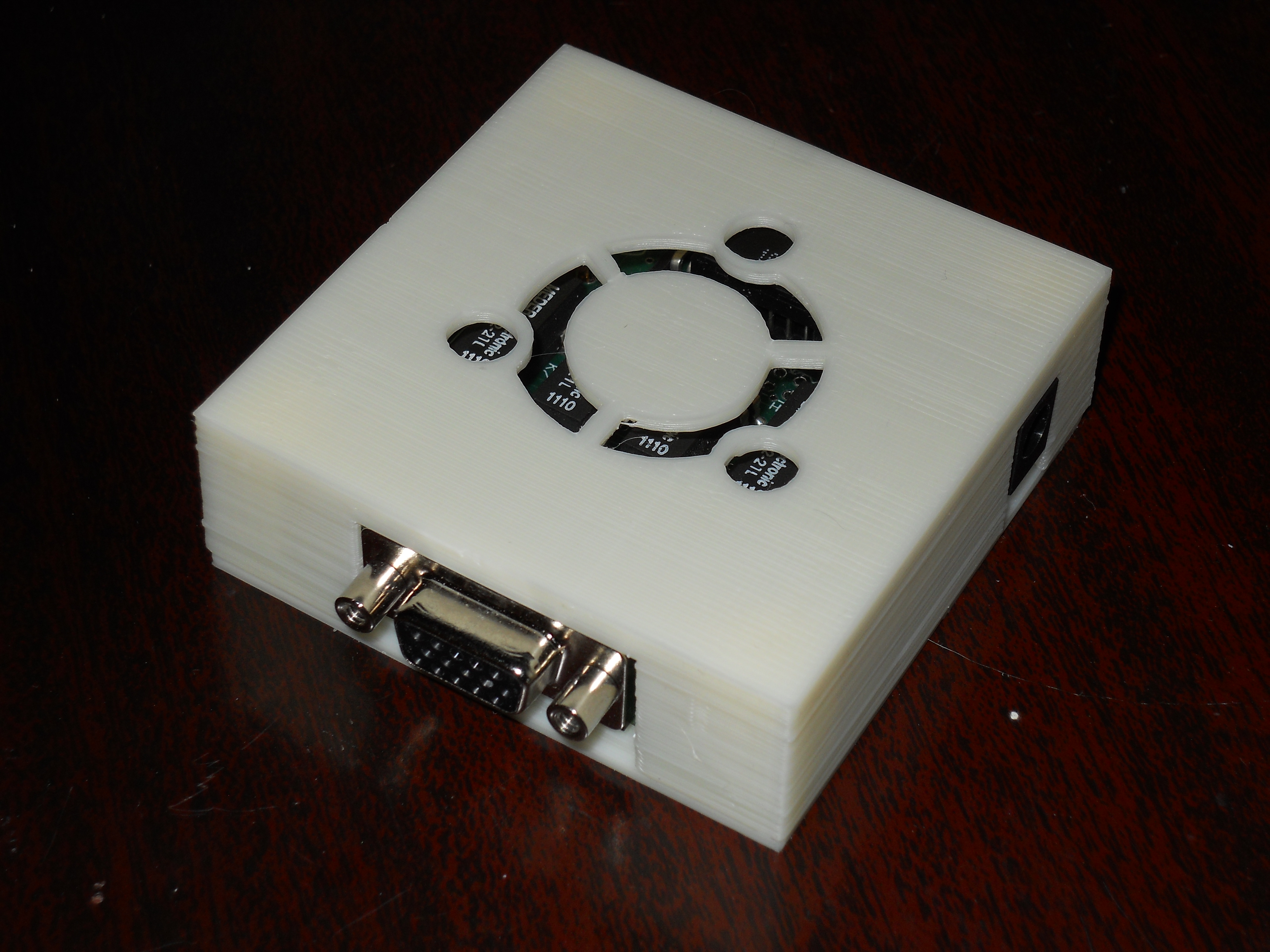
The VGA Switch (VGAS-01) is a switch which allows disconnecting a VGA display from a system under test. This is needed in order to test multimonitor hotplug, simulating a user plugging in an external display or projector.
Purpose
A device was required to allow simulating plugging and unplugging a monitor connected to a computer in an automated test framework. In addition, developers who were debugging or developing hotplug code were experiencing failures of the VGA connectors on their system. Using a switch device could eliminate that wear and tear, and make it much easier for the developer to simulate hotplugging.
A number of commercial products were tested to see whether they would work, including KVMs and remote monitor switches. None of these devices accurately simulated a complete disconnect of the display.
Implementation
The VGA Switch is very simple, using relays to connect and disconnect all 15 pins for the VGA connector. The VGA Switch has a manual rocker switch on the side to allow developers and testers to connect and disconnect the VGA device. For operation in an automated test system, the power supply for the switch is connected to a networked power outlet and switched under software control.
How to use it
To use, connect the device in-line with the VGA display, using an additional VGA cable.
License
This project is released as open hardware under the Apache 2.0 license
Source Code (Design Files)
All source files for this device are located In this git repository
Documents and source files include:
- Eagle CAD board design files
- Output files required for manufacturing the PC board
- Bill of materials (in the docs directory)
- A case design in openscad format, suitable for printing on a makerbot
Build Instructions
The Switch is simple to build. It uses all through-hole parts, and all parts mount on the top of the board.

Note for Rev 0:
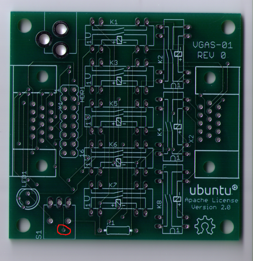
- You must place an insulator (a piece of tape will work) under the power switch body. The metal part of the switch body can short to a via on the PC board. The area that must be covered is circled in red on the photo.
Parts are most easily installed in this order:
- Install all DIP relays, paying attention to make sure the 'notched' end aligns with the marked end on the board. You can carefully flip the board over and support it with the relays while soldering the pins. Make sure that all the pins are in the holes before you start soldering.
- Next, install the two VGA connectors and solder them.
- Install the switch
- Install the power jack
- Install the Resistor for the LED. It has no required orientation.
- Install the LED. Make sure that the flat side of the LED base matches the outline on the PC board. The flat side is toward the VGA connector.
- Test the switch before you put it into the case
- Install the board in the plastic case, if you have one. Note that the hole pattern is not quite square, so the case bottom holes will only be aligned when oriented correctly.
OHW/VgaSwitch (last edited 2012-05-07 18:24:01 by vpn-98)